MAGNETIC ELASTICITY
compiled by Henryk Szubinski
compiled by Henryk Szubinski

With the data on the indentations of the visual cortex, there may be some applied function of what I'm showing here as the
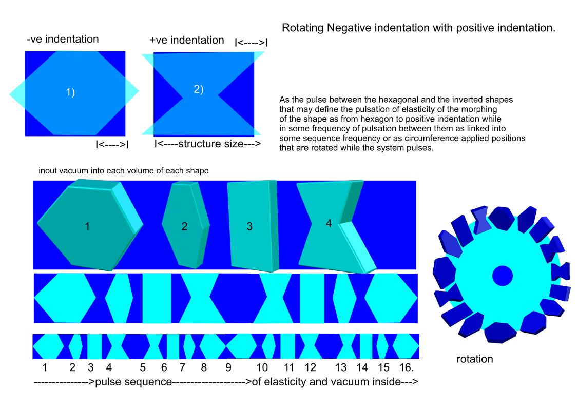
PULSE FREQUENCY of MORPHING the +ve and -ve indentations as related to the article that invented the +ve and -ve
indentations.
THE PULSE OCCURS WITH ELASTIC MAGNETS.
This could be the beginning of magnets that are concave as= positive indentation and
the convex magnets that are convex as negative indentation of the basic function to
be shaped that way may also reflect light along the sides of the magnetic interval spaces.
Interesting data that could be applied to the VISUAL FIELD OF INTERPLANETARY SPACE as MAGNETIC.
from:
https://www.researchgate.net/figure/234991163_fig1_FIG-1-Schematic-representation-of-shape-modification-by-indentation-a-convex-or
date 2017
December 03
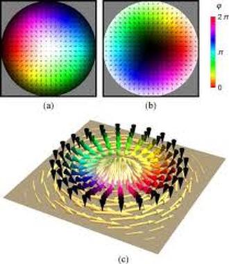
Recent developments in magnetoelectronics have fo- cused academic and industrial interest on properties of nanometer-scale ferromagnetic structures. Such structures, or nanomagnets, find vast applications in magnetic random ac- cess memory ͑ MRAM ͒ ͑ Ref. 2 ͒ and patterned magnetic storage media. 3 All these applications utilize the fact that below a certain size nanomagnets adopt a single domain magnetization configuration. In this configuration, the entire nanomagnet acts as a giant dipole. Several factors, namely, material parameters, shape, and size of magnetic nanostructures affect their magnetic properties. In addition to material properties such as saturation magnetization, exchange stiffness, and anisotropy, an understanding of the effect of shape on the magnetic properties of nanomagnets is crucial. Recent experimental 4 and modeling 5,6 results have demonstrated the complexity and variety of types of behavior originating from the symmetry and size of the nanomagnets. Such complexity is attributed to a competition between the exchange and magnetostatic interactions within each nanomagnet and has been summarized in the term ‘‘configurational anisotropy.’’ 7 Con- figurational anisotropy is a special class of shape anisotropy originating from the nonuniformity of the magnetization inside nanomagnets. To date, there has been no attempt to use this type of anisotropy for design in magnetic data storage applications. Such applications require the ferromagnetic elements to remain in a single or a quasisingle domain state for adequate write and read processes. If, on the other hand, the magnetization in the element adopts a flux-closing configuration, the readout process would be difficult if not impos- sible. Here, we present a method for controlling micromagnetic configuration in flat ferromagnetic square prisms made out of a soft, isotropic material, such as Ni Fe ͑ Permal- loy . To date, the most systematic investigation of the micromagnetics of flat square ferromagnetic prisms has been re- ported by Cowburn et al. , 5,8 who described various micromagnetic phases found in permalloy squares. 5 The aim of this current work is to take the understanding of configurational anisotropy further, by perturbing the shape of a nanomagnet in such a way that one micromagnetic phase would be energetically favored with respect to the others. This is particularly important for stabilizing a single domain phase in larger nanomagnets, which would otherwise adopt flux-closing configurations, such as a vortex. A very common method of ensuring magnetization alignment in nanomagnets or larger ferromagnetic structures is to increase the aspect ratio of the structures making them elongated in one direction. In this case, shape anisotropy forces the magnetization alignment although magnetization can still form domains due to rectangular edges. Chamfered or convex shapes are com- monly used to overcome edge effects, yet the influence of such shape modification has not been systematically studied. The method described here uses the indentation of two sides of a square, as shown in Fig. 1. A negative indentation is taken to signify convex or chamfered shapes ͑ a ͒ , whereas a positive indentation means concave structures ͑ b ͒ . To avoid mixing size and shape dependencies of the magnetization distribution in nanomagnets, the indentation is introduced while keeping the projected area of the nanomagnets constant. In this case, the size of the nanomagnet refers to the edge length of an unperturbed square, as shown in Fig. 1. In principle, the indentation, edge length, and thickness of the structure can all be varied. Here, we limit the investigation to edge length–indentation variations at a constant thickness of the nanostructures. The micromagnetics of the resulting system is studied and the results are compared with experimental measurements. The micromagnetic formalism is used to find the self- energy of a magnetization distribution inside the indented nanomagnets at remanence. The energy density E ( ) is given by the sum of the exchange and magnetostatic terms in Eq. ͑ 1 ͒ : 1 ϩ 2 all ͚ cells M គ ͑ គ Ј ͒ • D = ͑ គ Ј Ϫ គ ͒ • M គ ͑ គ ͒ , ͑ 1 ͒ where A and M s are the exchange stiffness and saturation magnetization, respectively. M គ is a Cartesian magnetization vector, and D = is a demagnetizing field tensor. It should be noted that no anisotropy or Zeeman terms were considered in these calculations, making them applicable to soft and isotropic ferromagnetic materials, such as Permalloy, at remanence. A finite-difference meshing with cubic cells was used in a steepest descent algorithm, 5,8 keeping the subdivisions to 5 nm or smaller. We performed simulations using Permalloy material parameters: M s ϭ 800 emu cm Ϫ 3 and A ϭ 1.05 ϫ 10 Ϫ 6 erg cm Ϫ 1 . Thus, our results can be directly compared to those for other isotropic ferromagnetic materials by scal- ing all lengths by a factor of ͱ A / M s 2 . The simulations were performed for flat Permalloy squares of a range of sizes and indentations keeping the thickness of the structures at 10 nm. Five distinct micromagnetic configurations were found. Figure 2 shows vector plots of magnetization distribution corresponding to each configuration. A complete flux-closing configuration termed ‘‘vortex’’ ͑ a ͒ is found in large nanomagnets. The magnetostatic energy is minimized by re- ducing the stray field around the structure, yet an energetically costly vortex core is formed in the middle. In smaller structures the magnetization does not manage to achieve a full flux closure leading to a buckle micromagnetic configuration ͑ b ͒ . The average direction of magnetization in that configuration is found to point along the axis of indentation, while s -configuration ͑ c ͒ points the average magnetization at an angle to that axis. Highly aligned and technologically important configurations emerge at very high concave or convex indentation values and are termed ‘‘flower’’ ͑ d ͒ and ‘‘leaf’’ ͑ e ͒ , respectively. It should be noted that in previously published work on micromagnetics of square planar nanostructures, 5,8 the leaf micromagnetic configuration was oriented along the diagonal of the square, while here, in leaf configuration, magnetization points along the concave inden- tation axis. In order to understand and verify the effect of indentation on magnetic properties of nanomagnets the structures are fabricated and their state of magnetization is measured as a function of applied magnetic field. The samples were fabricated by high-resolution electron beam lithography. Two layers of polymethylmethacrylate ͑ PMMA ͒ of differing molecular weights ͑ 495 000 and 950 000, respectively ͒ were spin coated on a single crystal silicon substrate. Arrays of indented squares were exposed using a JEOL 4000EX scanning/transmission electron microscope operated at 100 kV, followed by 11 s of development in a 7:3 solution of isopropyl alcohol ͑ IPA ͒ and water. 9 10 nm of Permalloy metal (Ni 80 Fe 20 ) was then deposited at a rate of 0.08 nm s Ϫ 1 by electron beam evaporation in an ultra- high-vacuum chamber with a base pressure of 5 ϫ 10 Ϫ 9 mbar. The evaporation pressure was approximately 1 ϫ 10 Ϫ 6 mbar. Magnetic film was removed from unexposed areas by ultrasonic assisted lift-off in acetone. An unpatterned sample was present in the chamber during the depo- sition to allow thickness, structure, and composition of the thin film to be examined. B-H looper, proton scattering experiments 10 and atomic force microscopy were used to check the film thickness, composition, and topography. It should be noted that no significant oxidation of Permalloy is found and that the thickness of deposited films can be quoted with Ϯ 0.5 nm accuracy. Magnetic properties of patterned and unpatterned samples are investigated by a high- sensitivity longitudinal magneto-optical Kerr effect ͑ MOKE ͒ magnetometer. 11 Continuous Permalloy films have a coercivity of approximately 2 Oe and anisotropy field of approximately 6 Oe. Patterned samples consisted of 10 m ϫ 10 m arrays of nanomagnets, where the edge-to-edge spacing between the structures was kept to at least the same size as the of structures to avoid mutual interaction. Figure 3 shows scanning electron micrographs of indented square nanomagnets of 100, 200, and 300 nm in size. The middle column of images in Fig. 3 shows square structures without any indentation. The MOKE magnetometer 11 measurements on such arrays yield two types of hysteresis loops, shown in Fig. 4. The shape of the hysteresis loops depends on a reversal mechanism, which in turn depends on the indentation value and size of the nanomagnets. These two hysteresis loop shapes are identified as curling reversal type ͑ a ͒ and square loop type b . Curling hysteresis loops resemble those obtained from ferromagnetic disks, 12,13 in which the magnetization is known to form full or partial flux closure states. Such hysteresis loops are obtained from nanomagnets with small indentations. Structures with large positive or negative indentations display remarkably square hysteresis loops stemming from a possible stabilization of a single domain micromagnetic configuration. Magnetization reversal is measured in structures of sizes between 100 and 400 nm with variable indentation between Ϫ 260 and ϩ 260 nm in the largest squares. Variation of coercive field and normalized remanent magnetization are shown in Fig. 5 as functions of indentation. Coercive field data show a similar trend for various structure sizes. One can distinguish two coercive field varia- tion regimes in Fig. 5 ͑ a ͒ , namely, large positive or negative indentation regime ( AB and DE ) and a small indentation regime ( BCD ). The coercive field values can be seen to decrease with decreasing indentation magnitude in the AB and DE regimes, while a BCD regime, where the square structures are perturbed only slightly, displays a peak in coercivity. The increase of coercivity values at large magnitude of indentation is thought to be due to an effect of artificially engineered configurational anisotropy. Such an effect renders hysteresis loops square ͓ Fig. 4 ͑ b ͔͒ by locking the magnetization at remanence in one direction as in the flower ͓ Fig. 2 ͑ d ͔͒ or leaf ͓ Fig. 2 ͑ c ͔͒ micromagnetic configurations. The exact reversal mechanism for this regime is not yet clear, however, the magnetization switching in the BCD regime can be ex- plained by a curling switching mode. In this mode the magnetization reaches a full or partial flux closure resulting in the hysteresis loops shown in Fig. 4 ͑ a ͒ . The increase of coercivity with indentation from B to C is, therefore, due to an increased difficulty of nucleating 14 a vortex or forming a buckle magnetization configuration. A decrease in coercivity from C to D could be associated with a change from one reversal mechanism to another allowing both to function in parallel. It should be noted that similar ‘‘W’’ shape curves are obtained by measuring remanence magnetization as shown in Fig. 5 ͑ b ͒ . The main feature of these curves is a clear saturation at large magnitudes of indentation. In order to understand the behavior of the remanence magnetization with varying indentation we use micromagnetic simulations described above to find the lowest energy micromagnetic configuration as a function of size and indentation for 10- nm-thick structures. Comparison of energies of the five configurations, shown in Fig. 2, leads to the construction of a micromagnetic phase diagram for flat indented square prisms made out of isotropic Permalloy ͑ Fig. 6 ͒ . Various areas on the phase diagram correspond to vortex, buckle, s, flower, and leaf configurations, and are separated by phase boundaries found from simulations ͑ lines ͒ . The phase boundaries between vortex and single domain configurations, such as leaf and flower, are asymmetric about the center of the phase diagram. Such an asymmetry indicates that the concave indentation is more efficient in preventing the formation of flux-closing configurations than a convex one. This can be intuitively understood by considering external field lines around the nanomagnets in the leaf and flower configurations. A concave or a positive indentation in that case leads to a better external field linkage and thereby stabilizes the magnetization at remanence. Another way to view this effect is to consider the indentation as a symmetry-breaking shape perturbation. Since micromagnetic phases, such as a vortex, have an odd symmetry about the indentation axis, the intro- duction of an indentation imposes an even symmetry leading to flower or leaf stabilization. However, nanomagnets with negative indentation have a closer resemblance to hexagons. Due to their greater symmetry, hexagonal shapes render the vortex configuration even more stable than perfect squares, which leads to the asymmetry of the phase diagram. It should be noted that the indentation scheme used here cannot be extended to values larger than the size of squares, thus a shaded area on the phase diagram indicates the inaccessible regions. In order to make any comparison between modeling results described above and experimental data in Fig. 5, one should appreciate conceptual differences between them. In constructing the micromagnetic phase diagram we found the ground state or the lowest energy configuration of the five configurations ͑ Fig. 2 ͒ . However, it is well known that ferromagnetic particles do not always adopt the lowest energy configurations due to issues such as nucleation. Thus, the micromagnetic phase boundaries in Fig. 6 represent the lower bound to the theoretical phase boundaries. In practice, the vortex configuration could fail to nucleate at smaller indentation values than are indicated by Fig. 6. A similar effect was previously observed in Permalloy circles 12 where a lower bound on the vortex-to-single-domain boundary was calculated and compared with results from MOKE hysteresis loop measurements. We use a similar approach for comparison of experimental and modeling results, however, the cri- terion for distinction between curling magnetization reversal via vortex or buckle and the square loop type is taken to be the value of normalized remanence ( M r / M s ), also known as squareness. It is known that the vortex configuration has a vanishing net magnetization at remanence. Additional simulations show that typical values of M r / M s for s, buckle, flower, and leaf configurations, are approximately ϳ 0.70, ϳ 0.85, ϳ 0.95, and ϳ 0.98, respectively. The last two values corresponding to the flower and leaf configurations are the only single domain configurations displaying a high net magnetization. Thus, one can split experimental data into two sets: one with M r / M s below 0.9 and one with M r / M s above 0.9. The nanostructures displaying M r / M s of 0.9 or higher are denoted as single domain structures ͑ filled circles in Fig. 6 ͒ , while those with M r / M s below 0.9 are considered to be in one of the curling configurations such as vortex, buckle, or the s configuration ͑ empty circles in Fig. 6 ͒ . The transition from high to low remanence on the negative indentation part of the phase diagram correlates with the leaf-to-vortex tran- sition phase boundary obtained from simulations. As men- tioned above, such a simulated phase boundary is merely a lower bound on the phase transition line. In terms of the indentation in square nanostructures, this boundary represents an upper limit to the magnitude of indentation in nanostructures preferring the vortex micromagnetic configuration. The leaf-to-vortex transition is, therefore, in a good agreement with micromagnetic simulations since no vortex or curling reversal is observed to the left of that phase boundary. In contrast, the experimental data on the right-hand side of the phase diagram seam to violate the predicted vortex-to- flower phase boundary since the open circles denoting curling configurations are observed to the right-hand side of the phase boundary. This apparent violation of the phase boundary can be attributed to structural imperfections, particularly to rounding of corners of the smaller nanostructures. From Fig. 3 one can infer that 100 nm structures have slightly rounded corners, which can facilitate the formation of curling configurations. The error in the indentation values and corner radii due to nanofabrication are estimated to be approximately Ϯ 5 nm and are represented by the size of the circles in Fig. 6. Taking into account the Ϯ 5 nm error, all but one point are in agreement with the simulation based phase diagram. Such good correlation between theory and experi- ment is very significant since all MOKE measurements in this article are performed on arrays of nanomagnets at room temperature. One of the most significant results of the comparison of experimental and modeling results is an apparent asymmetry in the phase diagram about the zero indentation line for both sets of data. As discussed above, such an asymmetry indicates that the single domain stabilization by indentation is more effective for concave ͑ positive ͒ indentations. Convex ͑ negative ͒ indentations result in a much shallower slope of the phase boundary between the vortex and the leaf. For concave indentations the effect of single domain stabilization is thought to be due to an enhanced configurational anisotropy. The form of the configurational anisotropy arising from shape manipulation is uniaxial due to the symmetry of the indentation. It should be noted that the single domain configurations such as leaf or flower were stabilized without changing the aspect ratio of the nanostructures. The shape manipulation by indentation used in this article is a demon- stration of a general concept of the shape optimization for designs of nanomagnet-based devices and future generations of MRAM or patterned magnetic media where a controlled state of magnetization at remanence is required. The authors would like to acknowledge useful discus- sions with C. Durkan, C. Sofield, and M. A. Perry.
Go to publication
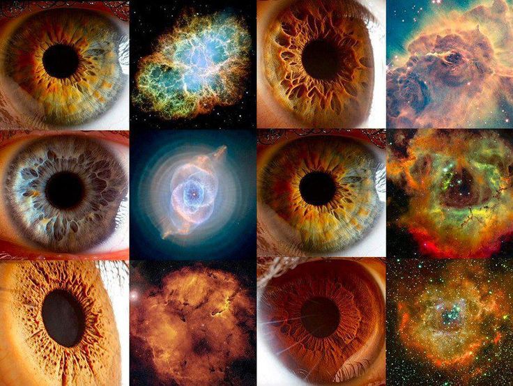
THE UNIVERSE MAY BE MAGNETIC
EYES and VISUAL FREE ENERGY as the definition of Nebulae or stars ,planets, dust and interplanetary space.
The human visual field may be directed by nano magnets as well as the brain being effected by the nano magnets
that appear as DENDRITES and AXONS.
Some applications of the visual cortex being the mix of ELASTICITY OF;
CONCAVE MAGNETS and
CONVEX MAGNETS with the
hole between them.Maybe that the universe began from a dipolar nano magnetic puncture.That the
universe may be MAGNETIC ,would imply that each particle from the begining stays the same as
space and that only the space changes as related to the first magnetic particles that remain in the
universe and that will continue to define the amount of magnetic SHAREING of each magnetic particles
that makes them stronger or weaker and that the tendency to one side as the begining = North polarity
of each magneto (magnetic particle) and that the universe would end as the negativo (negative magnetic
South polarity).
Or that: As seen by Hinduism;
We have collected so much material value that we are certain that we may avoid the pain of otherwise,
loosing it (as magnetic attraction) or,
not being able to navigate through the Earth and each of our belongings because we are made to avoid
pain (change of magnetic polarity) , we know the edges of the concave and convex pulsation where we
GO AROUND THEM because we prefer the soft curves more,
(as guided by magnetic fields) .
Also , that our eyes visual puncture connects the concave and convex in some in learned frequency
(wanting the ideal elasticity of magnets) ,set to the comparison with photons and why we seek the
opposite of pain in our human relations with each other (photons may also be magnetic space).
Theory by Henryk Szubinski
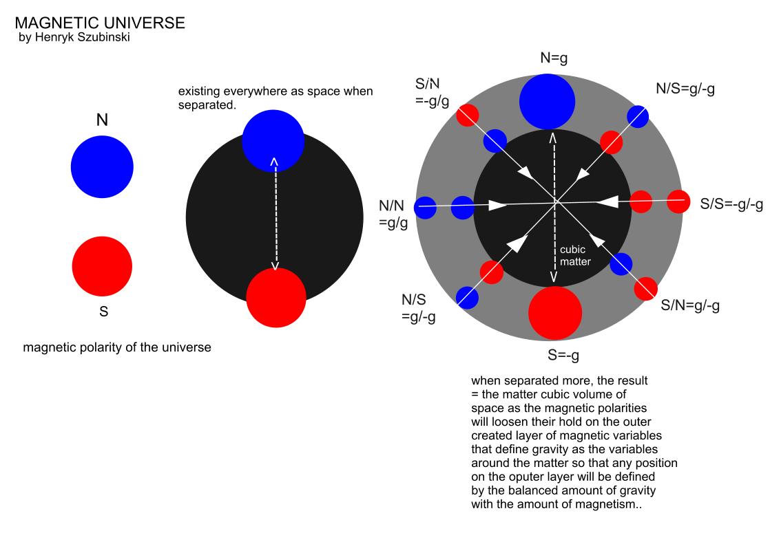
MAGNETIC SPACE everywhere and matter filled with space as amount of magnetism and the separation of
matter magnetism into strong magnetism and weak magnetism as inner and outer matter.
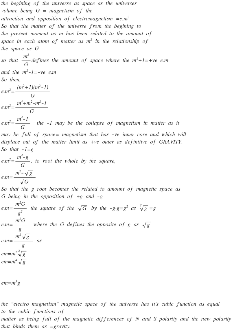
How space becomes matter and how magnetism becomes gravity.
Some background on Magnetism as the unknown force that defines the way we perceive the reality we
are placed in.
In Hinduism there are many mentions of the way we seek to be in the minimal amount of pain as related to
attraction and separation of the magnetic attraction and separation.
from;
http://www.hinduwebsite.com/hinduism/h_suffering.asp
2017
December 03
In Hinduism suffering or dukha, means the physical, mental and emotional instability and afflictions (klesas) that arise from the dualities and modifications of the mind and body. These modifications manifest variously in human life as pain and suffering, attraction and aversion, union and separation, desires, passions, emotions, aging, sickness, death, rebirth, etc.
According to Hinduism, suffering is an inescapable and integral part of life. The purpose of religious practice and various schools of Hinduism is to resolve human suffering that arises from samsara, which in a specific sense means the cycle of births and deaths and in a general sense, transient life. As long as man is caught in the phenomenal world of transient objects and appearances and becomes attached to them he has no escape from suffering.
Your Eyes then, as the indicator of the magnetic visual recognition of our amounts of positive or negative magnetism and their representations in space as that which
defines the magnetic universe.
you can read more on nano magnets
on
https://www.nanowerk.com/nanotechnology-news/newsid=47523.php
Pulses of electrons manipulate nanomagnets and store information(Nanowerk News) Magnets and magnetic phenomena underpin the vast majority of modern data storage, and the measurement scales for research focused on magnetic behaviors continue to shrink with the rest of digital technology. Skyrmions, for example, are a kind of nanomagnet, comprised of a spin-correlated ensemble of electrons acting as a topological magnet on certain microscopic surfaces. The precise properties, like spin orientation, of such nanomagnets can store information. But how might you go about moving or manipulating these nanomagnets at will to store the data you want?
New research from a German-U.S. collaboration now demonstrates such read/write ability using bursts of electrons, encoding topological energy structures robustly enough for potential data storage applications.
As the group reports this week in ("Ultrafast imprinting of topologically protected magnetic textures via pulsed electrons"), the magnetization of these ensemble excitations, or quasiparticles, is controlled by tailoring the profile of the electron pulses, varying either the total number of electrons or their width in space.